
It’s ambitious, it’s audacious, it’s a creepy cute way of not being able to detach from others staying in touch.
These two wristbands come as an inseparable pair, like star-crossed lovers. Each wristband senses your pulse, then transmits your heart’s beats-per-minute over a GSM network to the paired wristband, which will then vibrate the beat of your significant other’s heart onto your wrist. You can be alone, but together.
On its simplest level, this creation plays with the idea that the heartbeats synchronise when two people are very much in love. Will your heart rates sync?
Beyond that, however, it’s inspired by Sherry Turkle’s work of the same name. Focussed on computer dependency and alienation in a networked age, Alone Together asks the question – how much contact is too much? In an era of constant connection, is knowing your partners heart-rate a reassuring way of keeping in constant contact, or is it a gross overreach and food for our dependancy on always-on communication?
This is the story of the trials, tribulations and – eventually – failures of the wristband project.
Due to the work’s small scale, everything had to be planned in advance. The constraints of the materials mean that fallback options are limited, and therefore good planning (and good luck) would be vital to the success of the project.
The project had the following requirements:
Following a thorough investigation of potential parts, the following were purchased:
The parts list brought with it one complication – only one GSM module on the internet was small enough to work in the wristband format, and therefore if it should fail to work as expected, the entire GSM aspect of the project would fail.
As a fallback, I purchased a bluetooth module to allow a second way to send data.
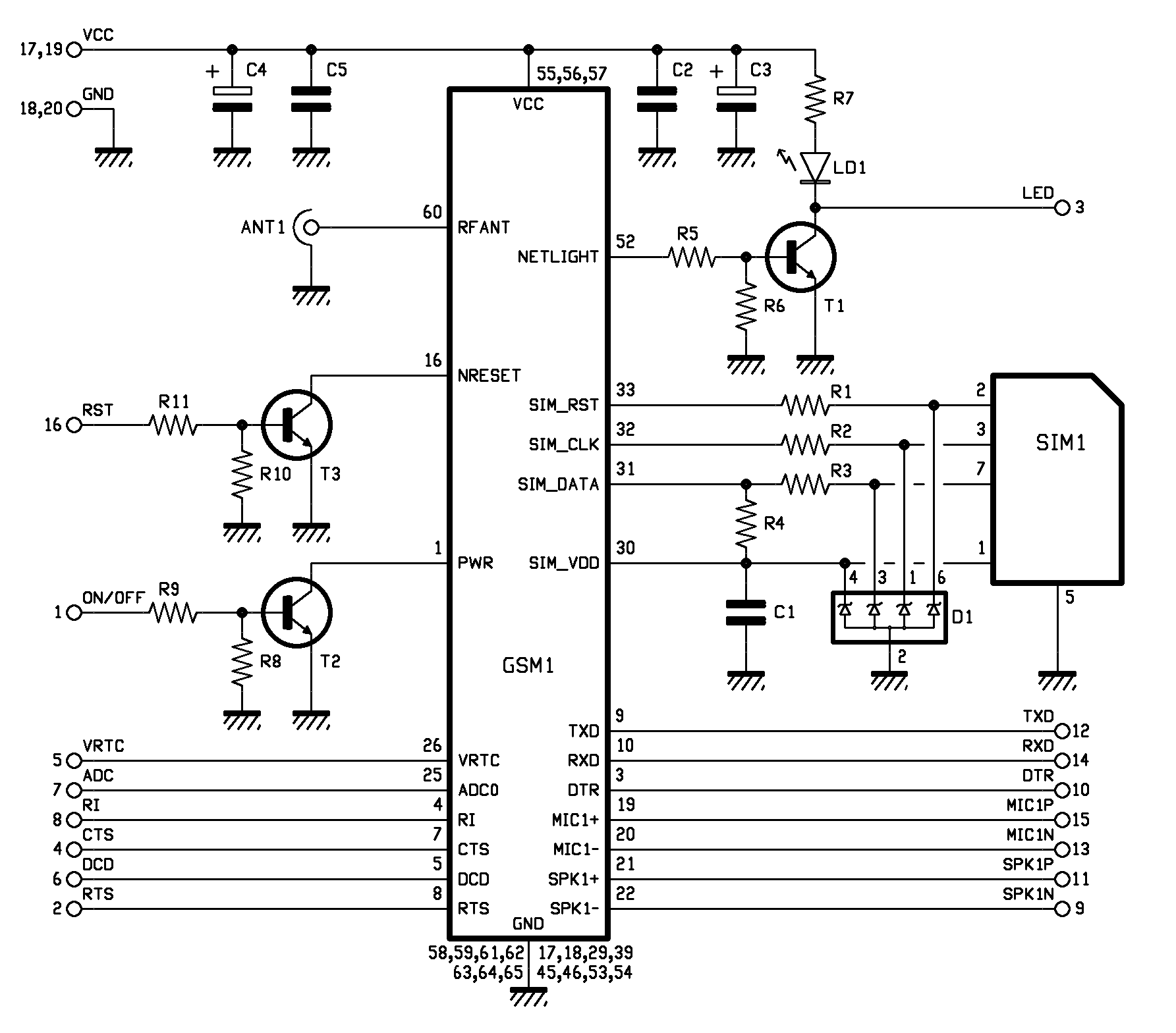
Having checked each products datasheets, I established that everything would be able to connect together, although the GSM board would need a separate power source (the 4.5V battery). These were the schematics for the project, which proved accurate throughout the project, despite other issues:

Below is a log of what happened during the project. It is written full of the emotions experience, as well as the events that occurred, while producing the work.
It’s happening! It’s really happening! The first part of the ultimate wristband has arrived. Hello moto(r)! From this humble (coin-sized) vibration motor comes great things.
A quick test on the +5V and Gnd pins to my Arduino Uno test rig shows that it works ferociously well. Also works on 3V (as expected) so will be fine with the TinyDuino.

It’s here – the beating heart of the project! A few boards swaps later (the TinyDuino needs to be defined as an Arduino Pro Mini in the IDE for the data to be sent correctly) and it’s flashing lights. Everything is good.
TinyDuino and vibration motor combined well. I was very happy showing it off – it was crazy oscillating. And then the vibration motor vibrated itself off of its ground wire, and that was the end of that.
The motor’s wires were actually wired into the vibration unit itself, which means there is no way to solder a cable back onto it. The vibration motor plays no further part in our story.
I ordered more. The delivery time was long.

If the annoyance of the vibration motor problem got my heart beating, then the arrival of the pulse monitor was just the thing I needed to show how infuriated I was. Unfortunately, the examples provided by the good people at Pulse Sensor was both verbose and bugged.
A few hours of debugging and chopping up the code got me a lean, mean, pulse-detecting machine. The Pulse Sensor now successfully grabs heart rates by sensing blood flow in the capillaries of the fingertips. A few more hours of testing proves that this can work on the wrist (and ears!), but needs to be in the exactly correct position. This is a turning point in the project, as it means the difference between an all-in-one embedded solution on the wrist, and a wristband with an external cable to the fingertip for the pulse.
Obviously the former is better, but I must prepare for both eventualities. Hopefully more testing will provide an answer.

It’s here! The second beating heart of the project. In fact, this is the beating heart, the TinyDuino can be the thinking brain.
Anyway, the GSM module has severely limited supported, while it’s supposed to be used with a GSM shield to break-out all of the parts and add audio abilities. The shield also adds bulk, however, making the whole project entirely impractical. Like a daring medieval warrior, I shall joust with this technology sans-shield.
I wish I had a GSM shield. Well, I don’t, because of the reasons listed above, but I wish they made them really small so I could use them.
That said, the GSM module without the shield isn’t that hard, based on the provided schematics. I only need to attach five wires to the GSM module from the Arduino – Tx, Rx, On, V+ and GND.
I’m having a hard time getting it to not complain about the voltage though, which I think is causing it to misbehave. 3V gives me undervoltage warnings, while 5V complains of overvoltage. The ideal operating range is between 4V and 4.5V, so I’ll have to drop down to that range until I get a 4.5V battery.
I came up with a diode-based solution to my voltage problems. No complaints, smooth running. Things are looking up from a GSM perspective. Had this diode solution not worked, I was all set to cut up a 9V battery, which is typically made up of six small 1.5V batteries in series. Cut this in half = perfect voltage. May use this for powering the final piece – much more versatile than a traditional 4.5V battery.
Aside from solving my voltage issues, I’ve cracked the included GSM libraries. I’m pretty much a GSM library wizard by this point. Again, the provided examples were not the best – it shipped with a “this method is deprecated” console print out every two seconds. I’ve isolated the real solution, however, and successfully implemented it. I can now send and receive text messages, reading their data and turning them into integers to be used in the vibration motor. Part of this is thanks to the wonderful C function: atoi.
Well, this is the theory, anyone – in actuality, my antenna hasn’t arrived, so I haven’t tested it yet.

Did you know GSM antennas come with different connections? Well, now I do.

Thanks to eBay, the antenna issue was quickly rectified. I now have an Arduino that connects to the GSM module, complete with antenna and SIM card. It’s experiencing intermittent issues, though. This happens on both of my GSM modules, so it’s probably a local issue or a wider problem. I’ve tested the voltage again, and tried powering it from a steady 4.5V external source, but the GMS module won’t boot correctly while the RX connection is attached.

A purchase of some male-to-female connectors hasn’t solved any problems. I thought that a loose connection may have been the problem, so instead of crocodile clips I’ve switch to MtF connectors to wire-up the Arduino and the GSM module. If I’m honest, they seem like a loose fit – I’m going to solder them.
Soldering was surprisingly easy, despite the tight angles. With no solder bridges and firm connection, I can now be absolutely sure that the issue is not with the wiring. Unfortunately, the RX problem continues.
I completely re-wrote the Arduino code, using a barebones solution to just receive SMS at this point. The “depreciated function” print out has gone, and the RX wire no longer needs to be disconnected for the module to boot. Unfortunately, there are still issues with the GSM module. Sometimes it will receive SMS messages, other times it won’t. Sometimes it successfully completes the booting cycle, sometimes it doesn’t.
What is the issue? I don’t know. I’m investigating.

My beautiful case turned up – a4th generation iPod Nano wristband. I noticed that the dimensions of this and my GSM module were roughly the same, so I bought a gel wristband for the Nano which gives me adequate “wiggle room” to squash in more technology if needs be. Some beautiful soldering has meant that the wires are connected really neatly. I’m quite proud. I’ve also coated the wires to the Pulse Sensor (to be mounted on the finger) using a nice cover, so the whole device looks pretty sleek.
Unfortunately, the GSM module is still being intermittent.
I’ve had a sustained period of uptime on the GSM module – I still can’t figure out why. I made no changes to the code or the physical hardware, but today it’s running perfectly. With the SMS messages coming in successfully, I’ve hit another problem – the Arduino is having difficulty controlling the timing of the vibrations with checking for new SMS messages. There will be three evenly-spaced vibrations, then one that actually adheres to the beats-per-minute of the heart.
Obviously this is a drawback of the non-threading Arduino device.
The GSM module has not been working at all today. Nothing has changed in the set-up since when it was working. Issues have been raised on forums and with manufacturers, no feedback as yet.
While I can’t get the GSM module working properly, I can fix the threading issues. I’ve decided to elongate the cycle time by adding a loop which must run for 30 simulated heart-beats.
This means the GSM module doesn’t have a chance to continue its SMS-finding algorithms until 30 beats have passed, which means for every 30 correctly-timed beats, three are errant thanks to the SIM900 cycle. That’s an acceptable compromise between update periods and beats.
I also added a new library to speed up the DigitalWrite process. It’s been suggested that the Digital Write, when used rapidly, can cause slowdown, so this new library should quicken things up and avoid bottlenecks.
I’m sitll not having any luck with the GSM module. There has been no answer from support (disappointing), while the module has only worked for an hour or so over the past six days.
My current theory is that it could be signal issues. The antenna may be too weak to pick up a decent signal, especially in the areas I have been testing it. Both at my house and in the lab, Vodafone signal is weak even on a modern smartphone. This would explain the lack of success in completing the GSM module’s cycle intermittently.
I’ve begun desperately constructing a back-up – a simple Arduino program that reads pulses and flashes lights. The pulse rate syncs with a Processing sketch that records it as an integer in a file.
This file syncs over the internet to another computer, linked to another Arduino, which then flashes out the pulse rate.
At the same time, the second Arduino will record a pulse rate, save it to a file, sync it over the internet and send it back to the first one. The result is two syncing Arduinos, vibrating their users’ pulse rates to their pair.

Unfortunately, the GSM module never came online, which meant that I had to go with the fall-back solution. With no time to make the devices look pretty, it’s currently two Arduinos, two computers and a few wires.
However, I have plans to continue the work, and alter it for a gallery-space. Currently, I plan on renaming “The Artist’s Heart is in Residence”, in honour of the work by Marina Abramovic, and present only the vibrating part of the device in the gallery.
This vibration be installed inside a real animal heart, to create symbolic link between the digital heart rate and the physical, flesh-and-blood heart. The motor will sync with my heart-rate in real-time (which will be collected using the wristband above, and sent via GSM, bluetooth or another type of internet connection). Visitors will be encouraged to touch the heart, and feel my pulse at any time.
This change also shifts the question of the piece from inter-personal relationships to that of wider social broadcasting – how much of ourselves is too much to digitally share?